Pressure and Flow Control Loop Interaction
Weird control strategies are sometimes used in lieu of proper tuning to address process interactions. A customer contacted me with a question about such a control strategy. She explained that a blower was being used for maintaining (negative) air pressure in a common clean-air header, and to deliver air flow to process equipment. The blower was fitted with a variable-frequency drive, which was used to control the pressure inside the clean-air duct, and a control valve was used to bypass air around the process equipment to control air flow (Figure 1).
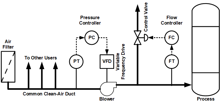
Figure 1. Process & Control Diagram
The weird part of the design was that the control strategy had an interlock that allowed only one of the two controllers to run in automatic control mode at any time. My customer was told by the company who installed the system that the interlock was necessary because interaction between the pressure and flow control loops would cause system instability. She asked me to come to her plant to determine if there was any possible way to control duct pressure and air flow rate at the same time, considering how the two variables interact on each other.
To explore the problem on site, we did step changes on the two controller outputs, one at a time, while recording pressure and flow. Then we reviewed the data to decide on the best path forward. It turned out that changes in the pressure controller’s output strongly affected both pressure and flow, but changes in the flow controller’s output mostly affected the flow, with a lesser, but still significant, effect on pressure.
The dynamic response of the two processes (dead time and time constant) was virtually identical. This meant that if both control loops were tuned aggressively, there would be a significant chance of cyclical interaction occurring between the two loops. Needless to say, both control loops were found to be tuned very aggressively, which would most likely cause cyclical interaction. If the process dynamics were significantly different from each other, cyclical interaction would not be such a concern.
We decided to suppress any possible cyclical interaction by tuning the two loops to have different response times (one fast and the other slow) which will also cause one of the loops to have a significantly damped response (which is very good for maintaining stability).
Since most of the disturbances were caused by other users on the common clean-air duct, we decided to tune the pressure controller for a fast response. For this we used the Cohen-Coon tuning rules with a stability margin of 2. Once the pressure controller was tuned, we put it in automatic control mode and redid the step tests on the flow loop, to include the effect of the pressure controller running/interacting in automatic control. We tuned the flow loop for a slow and damped response (five times slower than the pressure loop’s response) using the Lambda tuning rules.
When both control loops were properly tuned, we removed the interlock and put the flow loop in automatic control. As we expected, the system remained perfectly stable. We stopped and restarted one of the other clean-air users and the system behaved perfectly with not a hint of cycling or instability. The operators were delighted because they would no longer have to manually control either flow or pressure. In addition, the variability in air flow rate and duct pressure was significantly reduced (Figure 2).
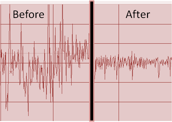
Figure 2. Improvement in flow rate variability
The takeaway here is that control problems that may seem insurmountable can sometimes be overcome, given the right knowledge and correct approach.
Stay tuned!
Jacques Smuts Founder and Principal Consultant, OptiControls
Author of Process Control for Practitioners
