Equal Percentage Control Valves and Applications
Far too often, equal percentage control valves are found in applications where linear control valves should have been used. This article explains equal percentage control valves and sets guidelines for their use.
What is an Equal Percentage Control Valve?
The relationship between valve stem position and the flow rate through a control valve is described by a curve called the valve’s flow characteristic curve, or simply the valve characteristic. An equal percentage flow characteristic is a nonlinear curve of which the slope increases as the valve opens, while a linear flow characteristic is a straight line (Figure 1).
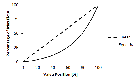
Figure 1. Equal percentage and linear flow characteristics.
Control valves manipulate the rate of liquid/gas flow through them by altering the open area through which the liquid/gas passes. Linear valves increase the open area linearly with valve travel, while equal percentage valves open progressively more area with valve travel (Figure 2).
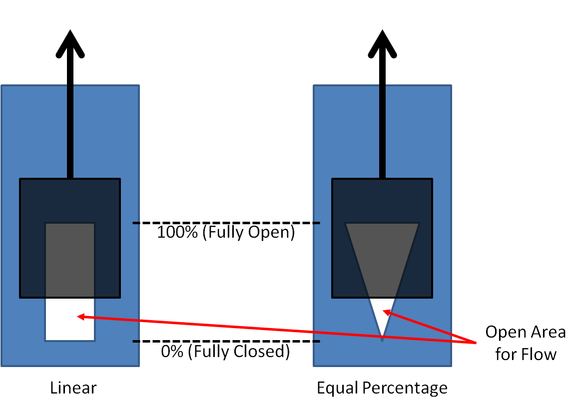
Figure 2. Port shapes of linear and equal percentage valves.
Why do we need Equal Percentage Valves?
PID controllers are linear devices and for optimal performance, the process should behave linearly too. That is, if the controller output changes from 10% to 20%, the process should respond just as much as it would if the controller output changes from 80% to 90%. From this requirement, it seems that linear control valves should be sufficient.
However, up to now we have been talking about the inherent/design flow characteristic of control valves. This is the flow characteristic that a valve exhibits if the pressure difference across it remains constant throughout its operating range. But in practice this is often not the case. The pressure difference across a valve is often a function of flow, and it changes with valve position. Consequently, the inherent flow characteristic is often distorted by the process and we refer to the resulting curve as the installed valve characteristic.
So we have to refine our linearity requirement to reflect the installed valve characteristic. Sometimes we need to use a control valve with an equal percentage inherent characteristic to obtain a linear installed characteristic. Two distinctly different scenarios follow.
Scenario 1a
Consider a centrifugal pump for providing pressure, and a control valve for controlling the flow (Figure 3). As the pump delivers more flow, its capability for generating pressure decreases. Therefore the pressure differential across the control valve is high at low flow rates; and it is low at high flow rates. An equal percentage valve can offset this change in differential pressure to exhibit a more linear installed characteristic.
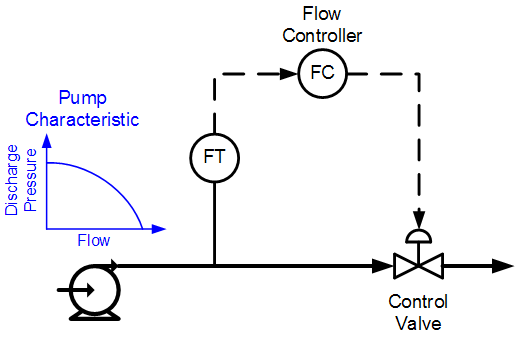
Figure 3. Simple flow control loop with centrifugal pump.
Scenario 1b
However, we can’t just assume that because we have a centrifugal pump, we need an equal percentage valve. If the system pressure (backpressure) downstream of the valve remains high, for example when pumping into a pressurized system, the pump will likely stay high on its curve, and the pressure across the control valve will not change appreciably. In this case a linear valve might be a better choice.
If we consider the pressure differential across the valve versus flow, we can make the right choice in Scenarios 1a and 1b. If the pressure differential remains reasonably constant, a linear valve is required (but please read Scenario 2 below). If the pressure differential drops by more than 50%, equal percentage can provide better linearity. To remove the guesswork, use valve-sizing software. The software should allow you to specify a few pressure-differential versus flow points and based on that, it will recommend the best valve for the application.
Scenario 2
Let’s consider a steam-condensing heat exchanger (Figure 4). The pressure upstream of the valve is kept constant by the boiler and steam pressure controller. The pressure downstream of the valve is determined by the condensate temperature, which is roughly equal to the outlet temperature, which is controlled to a constant setpoint.
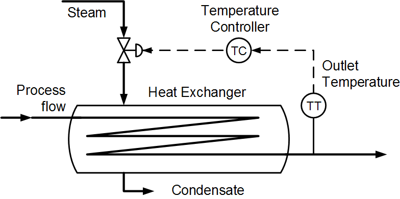
Figure 4. Steam-condensing heat exchanger.
In other words, the pressure differential across the steam control valve remains relatively constant, regardless of the flow. Should we then use a linear valve. Well, we should actually use ratio control in which we control the steam flow rate as a ratio of the process flow rate and use a linear valve, but that is another story. Most heat exchanger control designs are as simple as shown in Figure 4.
Even though the constant differential pressure across the valve calls for a linear control valve, this process calls for an equal percentage valve. At low process flow rates, the outlet temperature is very sensitive to changes in steam flow. At high process flow rates, the steam flow must be changed much more to affect the heater outlet temperature to the same degree. This can be accomplished by using an equal percentage control valve. At small valve openings, the valve sensitivity is very low, which cancels the high sensitivity of the process. The valve sensitivity increases as the valve opens more – which is exactly what is required because the sensitivity of our heat exchanger decreases with increased process flow rates.
Conclusion
An equal percentage control valve should be used when the pressure differential across the valve decreases with increases in flow rate. Valve sizing software should be able to find the right valve characteristic for the job. Also, equal percentage control valves should be used in control loops of which the process gain decreases with increases in flow rate. If none of these conditions apply, the loop is likely better off with a linear control valve.
Stay tuned!
Jacques Smuts
Principal consultant of OptiControls, and author of Process Control for Practitioners.

Thank you for this great post. In your 2nd scenario, let’s say we initially installed an equal-percentage valve and outputted directly to it from the TC. Later, we decide to convert it to a cascade loop with a flow controller as the secondary, but the valve is still equal-percentage. Does this mean we have just created a rather nonlinear process out of a linear one? If so, that sure sounds like an easy mistake to make!
Donald – Yes you are correct. Enclosing the equal-percentage valve in a cascaded flow control loop creates a linear relationship between the temperature controller’s output and steam flow rate. Then the process’ inherent nonlinearity is not being canceled, creating a nonlinear control loop. As you say, this is an easy mistake to make. However, most facilities rarely use cascade control (even where it can be beneficial).
Donald, if your TC has the capability of adding an f(x) function generator, your steam flow controller can control the Equal Percentage (EP) valve AS IF it was a Linear valve. i.e.: x,y data pairs would input flow demand & output position demand; this data can be calc’d, but since your proposal already includes an FT it’s better to use online testing. That way, the flow controller will be linear at every flow.
Then to recover the benefit of an EP valve (low change in flow demand at low “Process flow” rates; high change at high rates) you can add one more f(x) to the flow setpoint calc. (between the 2 cascaded loops). This set of x,y pairs would mimic the curve of an EP valve, thus treating the downstream flow controller & valve AS IF it were a complex EP valve, yet retaining the benefit of a fast flow controller to overcome unexpected system non-linearities and upsets (e.g.: valve wear, temporary change in steam supply pressure).
Can some one explain as to which one is better . Equal percentage characteristics through a valve or obtaining it through an actuator ? This is for cooling application in a fan coil unit.
Atif – It is better to have a valve with the desired characteristic. If you use a positioner to imitate an equal percentage characteristic you’ll find that it cannot provide the small flow resolution at the low end because of the limited mechanical resolution of the valve.
Jacques,
I hope this message finds you well. Thank you for the excellent essay. From your conclusions, I’m gathering that a vent valve controlling tank pressure on a PI controller, where the valve is close coupled to the tank, should probably have a linear plug/trim. Here, dP across the valve is directly related to flow rate out of the tank because a higher tank pressure creates a higher flow rate. In my specific application, the vent valve exhausts to atmosphere, so flow losses into and out of the valve are negligible. So, dP is simply equal to the tank pressure (PV). Would you agree with this? I ask because we installed an equal percentage plug because we were worried the valve would be too big, however we’re finding that P gain needs to be very high in order for the valve to open enough at lower tank pressures, and even then we’re seeing offset. We haven’t had time to increase I gain to compensate but maybe that could work?
Joe: Yes, if you end up with offset, increasing Integral Gain (or decreasing Integral Time) will most likely help. However, it appears that you need to use controller gain scheduling based on tank pressure. Low pressure requires a high gain and high pressures requires a low gain. I have several articles on this blog site that talk about gain scheduling, for example: https://blog.opticontrols.com/archives/182. Or you can search for “scheduling” in the site’s search box to see them all. Click the “Older Entries” link at the top of the page to scroll through them one at a time.