7. Control Strategies
Caster Level Control Improvement
Recently, I helped a foundry with a level control problem in their casting process. A batch of metal is melted in a furnace, after which the furnace is slowly tilted to pour the metal into a trough above the caster. The level of molten metal in the caster trough must be kept constant so that the metal flows into the mould at a constant rate. This is done by manipulating the tilt rate of the furnace. The foundry had problems maintaining a constant level in the caster trough. An investigation of the system and equipment revealed the problem.
System Description
The level of the molten metal in the casting trough is measured with a non-contact level sensor and sent to a PID controller. The controller compares the level to its setpoint and manipulates the valve that controls the furnace’s tilt rate (Figure 1). If the level is below setpoint, the PID controller opens the valve more and the furnace tilts faster. Likewise, if the level is above setpoint, the valve position is reduced.
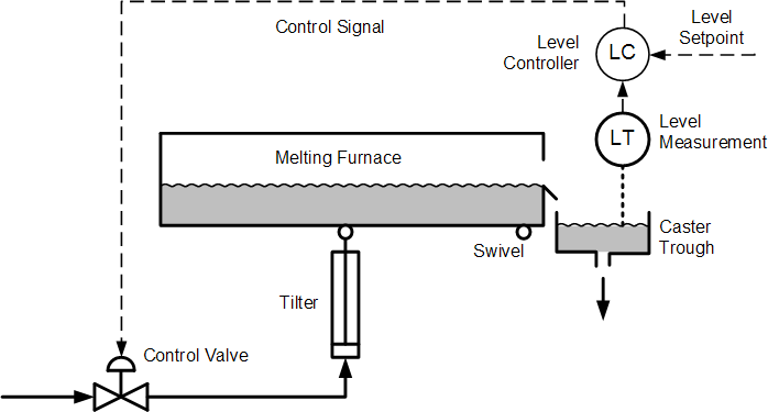
Figure 1. Caster Trough Level Control (click to enlarge)
The Problem
The tuning parameters of any PID controller should be set according to the gain and dynamics of the process it is controlling. A control loop can tolerate small changes in process characteristics, but large changes will cause poor control, unless the control design somehow compensates for this. And herein lay the problem – during the casting process the process gain changed vastly.
At the beginning of the cast, when the molten metal in the furnace has a large surface area, a 1° change in tilt angle will pour a large quantity of metal into the caster trough. At the end of the cast, when the furnace is tilted significantly and the molten metal has a small surface area, a 1° change in tilt angle will pour only a small quantity of metal (Figure 2). This causes the process gain to change by a factor of almost 10 during the casting process.
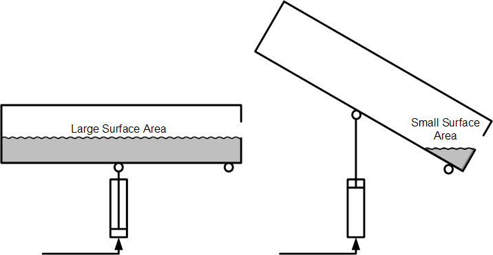
Figure 2. Origin of Process Nonlinearity
It is impossible to have good feedback control from a simple control loop if the process gain changes this much. The loop performance will range from being close to instability (when the process gain is high at low tilt angles early in the cast) to being very sluggish (when the process gain is low at high tilt angles late in the cast). This is why the foundry had so much trouble with this control loop.
The Solution
The solution was to either use gain scheduling on the controller or to implement a linearizer between the controller output and the process. Both of these would essentially keep the loop gain constant by either changing the controller gain based on tilt angle, or by compensating for the nonlinear process gain at different tilt angles. To simplify tuning, we chose the linearizer. The linearizer would multiply the controller output by a certain factor that would be changed automatically, based on the furnace’s tilt position (Figure 3).
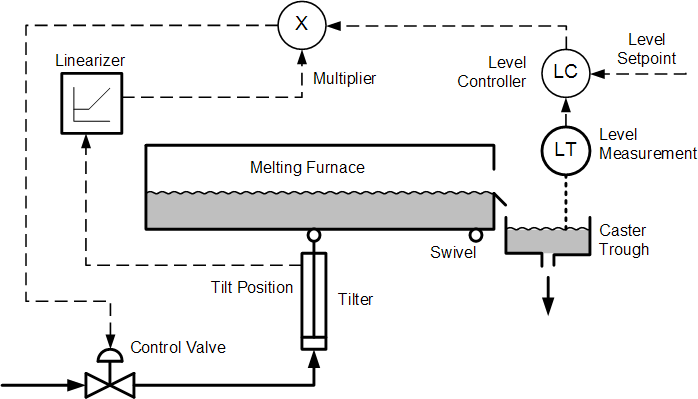
Figure 3. Level Control Improvement through Linearization
We used trigonometry to calculate the appropriate multiplier for different tilt positions and implemented this into a function generator block in the control system. After this the loop was linear and the control performance vastly improved.
When tuning control loops, it is always important to understand the process and its characteristics, and how these characteristics might change in relation to the process conditions. A process control practitioner should always look for the true reason of poor control. In many cases this goes far beyond controller tuning.
Find out more about process nonlinearity, gain scheduling, controller tuning, and much more in my book Process Control for Practitioners.
Stay tuned!
Jacques Smuts
Principal Consultant
OptiControls
