PID Controllers Explained
PID controllers are named after the Proportional, Integral and Derivative control modes they have. They are used in most automatic process control applications in industry. PID controllers can be used to regulate flow, temperature, pressure, level, and many other industrial process variables. This blog reviews the design of PID controllers and explains the P, I and D control modes used in them.
Manual Control
Without automatic controllers, all regulation tasks will have to be done manually. For example: To keep constant the temperature of water discharged from an industrial gas-fired heater, an operator will have to watch a temperature gauge and adjust a fuel gas valve accordingly (Figure 1). If the water temperature becomes too high for some reason, the operator has to close the gas valve a bit – just enough to bring the temperature back to the desired value. If the water becomes too cold, he has to open the gas valve.

Figure 1. An operator doing manual control.
Feedback Control
The control task done by the operator is called feedback control, because the operator changes the firing rate based on feedback that he gets from the process via the temperature gauge. Feedback control can be done manually as described here, but it is commonly done automatically, as will be explained in the next section.
Control Loop
The operator, valve, process, and temperature gauge forms a control loop. Any change the operator makes to the gas valve affects the temperature which is fed back to the operator, thereby closing the loop.
Automatic Control
To relieve our operator from the tedious task of manual control, we should automate the control loop. This is done as follows:
- Install an electronic temperature measurement device.
- Automate the gas valve by adding an actuator (and perhaps a positioner) to it so that it can be driven electronically.
- Install a controller (in this case a PID controller), and connect it to the electronic temperature measurement and the automated control valve.
A PID controller has a Set Point (SP) that the operator can set to the desired temperature. The Controller’s Output (CO) sets the position of the control valve. And the temperature measurement, called the Process Variable (PV) gives the controller its much-needed feedback. The process variable and controller output are commonly transmitted via 4 – 20mA signals, or via digital commands on a Fieldbus.
When everything is up and running, the PID controller compares the process variable to its set point and calculates the difference between the two signals, also called the Error (E).
Then, based on the Error and the PID controller’s tuning constants, the controller calculates an appropriate controller output that opens the control valve to the right position for keeping the temperature at the set point. If the temperature should rise above its set point, the controller will reduce the valve position and vice versa.

Figure 2. A PID controller doing automatic control.
PID Control
PID controllers have three control modes:
- Proportional Control
- Integral Control
- Derivative Control
Each of the three modes reacts differently to the error. The amount of response produced by each control mode is adjustable by changing the controller’s tuning settings.
Proportional Control Mode
The proportional control mode is in most cases the main driving force in a controller. It changes the controller output in proportion to the error (Figure 3). If the error gets bigger, the control action gets bigger. This makes a lot of sense, since more control action is needed to correct large errors.
The adjustable setting for proportional control is called the Controller Gain (Kc). A higher controller gain will increase the amount of proportional control action for a given error. If the controller gain is set too high the control loop will begin oscillating and become unstable. If the controller gain is set too low, it will not respond adequately to disturbances or set point changes.
![]()

Figure 3. Proportional control action.
Adjusting the controller gain setting actually influences the integral and derivative control modes too. That is why this parameter is called controller gain and not proportional gain.
Proportional Band
While most controllers use controller gain (Kc) as the proportional setting, some controllers use Proportional Band (PB), which is expressed in percent. Table 1 shows the relationship between Kc and PB.
Controller Gain (Kc) |
Proportional Band (PB) % |
| 0.1 | 1000 |
| 0.2 | 500 |
| 0.5 | 200 |
| 1 | 100 |
| 2 | 50 |
| 5 | 20 |
| 10 | 10 |
Table 1. Relationship between Kc and PB
Proportional-only Controller
Proportional controllers are simple to understand and easy to tune. The controller output is simply the output of the proportional control mode, plus a bias. The bias is needed so that the controller can maintain an output (say at 50%) while there is no error (set point = process variable).
![]()

Figure 4. A proportional-only controller algorithm.
The use of proportional control alone has a large drawback – offset. Offset is a sustained error that cannot be eliminated by proportional control alone. For example, let’s consider controlling the water level in the tank in Figure 5 with a proportional-only controller. As long as the flow out of the tank remains constant, the level will remain at its set point.

Figure 5. Level control, with operator causing a disturbance.
But, if the operator should increase the flow out of the tank, the tank level will begin to decrease due to the imbalance between inflow and outflow. While the tank level decreases, the error increases and our proportional controller increases the controller output proportional to this error. Consequently, the valve controlling the flow into the tank opens wider and more water flows into the tank.
As the level continues to decrease, the valve continues to open until it gets to a point where the inflow again matches the outflow. At this point the tank level (and error) will remain constant. Because the error remains constant our P-controller will keep its output constant and the control valve will hold its position. The system now remains at balance, but the tank level remains below its set point. This residual sustained error is called Offset.
Figure 6 shows the effect of a sudden decrease in fuel gas pressure to the process heater described earlier, and the response of a p-only controller. The decrease in fuel-gas pressure reduces the firing rate and the heater outlet temperature decreases. This creates and error to which the controller responds. However, a new balance-point between control action and error is found and the temperature offset is not eliminated by the proportional controller.

Figure 6. A proportional controller’s response to a disturbance.
Under proportional-only control, the offset will remain until the operator manually changes the bias on the controller’s output to remove the offset. This is typically done by putting the controller in manual mode, changing its output manually until the error is zero, and then putting it back in automatic control. It is said that the operator manually “Resets” the controller.
Integral Control Mode
The need for manual reset as described above led to the development of automatic reset or the Integral Control Mode, as we know it today. As long as there is an error present (process variable not at set point), the integral control mode will continuously increment or decrement the controller’s output to reduce the error. Given enough time, integral action will drive the controller output far enough to reduce the error to zero.
If the error is large, the integral mode will increment/decrement the controller output fast, if the error is small, the changes will be slower. For a given error, the speed of the integral action is set by the controller’s integral time setting (TI). A large value of TI (long integral time) results in a slow integral action, and a small value of TI (short integral time) results in a fast integral action (Figure 7). If the integral time is set too long, the controller will be sluggish, if it is set too short, the control loop will oscillate and become unstable. In the figure, TS is the control algorithm’s execution interval, sometimes called sampling time or scan time.
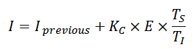

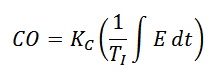
Figure 7. Integral control action and an integral-only controller’s equation.
Most controllers use integral time in minutes as the unit of measure for integral control, but some others use integral time in seconds, integral gain in repeats per minute or repeats per second. Table 2 compares the different integral units of measure.
Integral Time |
Integral Gain |
||
Minutes |
Seconds |
Rep / Min |
Rep / Sec |
| 0.05 | 3 | 20 | 0.333 |
| 0.1 | 6 | 10 | 0.167 |
| 0.2 | 12 | 5 | 0.0833 |
| 0.5 | 30 | 2 | 0.0333 |
| 1 | 60 | 1 | 0.0167 |
| 2 | 120 | 0.5 | 0.00833 |
| 5 | 300 | 0.2 | 0.00333 |
| 10 | 600 | 0.1 | 0.00167 |
| 20 | 1200 | 0.05 | 0.00083 |
Table 2. Units of the integral control mode.
Proportional + Integral Controller
Commonly called the PI controller, its controller output is made up of the sum of the proportional and integral control actions (Figure 8).
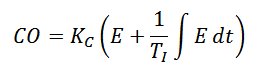

Figure 8. The PI controller algorithm.
Figure 9 shows how the integral mode continues to increment the controller’s output to bring the heater outlet temperature back to its set point. Compared to Figure 6, it is clear how Integral control eliminates offset.

Figure 9. A PI controller’s response to a disturbance.
Derivative Control Mode
The third control mode in a PID controller is derivative. Derivative control is rarely used in controlling processes, but it is used often in motion control. For process control, it is not absolutely required, is very sensitive to measurement noise and it makes trial-and-error tuning more difficult. See https://blog.opticontrols.com/archives/153 for more detail. Nevertheless, using the derivative control mode of a controller can make a control loop respond a little faster than with PI control alone.
The derivative control mode produces an output based on the rate of change of the error (Figure 10). Derivative mode is sometimes called Rate. The derivative mode produces more control action if the error changes at a faster rate. If there is no change in the error, the derivative action is zero. The derivative mode has an adjustable setting called Derivative Time (TD). The larger the derivative time setting, the more derivative action is produced. A derivative time setting of zero effectively turns off this mode. If the derivative time is set too long, oscillations will occur and the control loop will run unstable. Again TS is the controller’s execution interval.
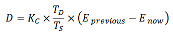

Figure 10. Derivative control action.
Two units of measure are used for the derivative setting of a controller: minutes and seconds.
Proportional + Integral + Derivative Controller
Commonly called the PID controller, its controller output is made up of the sum of the proportional, integral, and derivative control actions (Figure 11). There are other configurations too. See https://blog.opticontrols.com/archives/124 for a description.
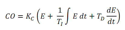

Figure 11. The Standard (Noninteractive) PID controller algorithm.
PID control provides more control action sooner than what is possible with P or PI control. This reduces the effect of a disturbance, and shortens the time it takes for the level to return to its set point.

Figure 12. A PID controller’s response to a disturbance.
Figure 13 compares the recovery under P, PI, and PID control of the process heater outlet temperature (PV) after a sudden change in fuel gas pressure as described above.

Figure 13. The result of a P, PI, and PID controllers’ response to a disturbance.
Stay tuned!
Jacques Smuts – Author of the book Process Control for Practitioners

hye, I’m looking forward to know more about PID controller and try to find a suitable books or reference regarding this topic since i teach control engineering subject. thanks
Mohd, you could take a look at this book: Process Control for Practitioners
Jacques
while I appreciate for the physical example given for the proportional control action, could you please explain the interal action by physical explanation? From mathematical, the reset action is not comprehensible.
Maiti: Here is a practical example of everyday integral action. You perform a type of integral action when you change your shower water’s temperature. Let’s say the water is way too cold. You might know from experience you have to turn the hot water tap at least 1/4 turn. This is equivalent to proportional action. Then the temperature might be closer, but still not exactly on target. So you slowly turn the tap some more. The closer you get to the desired temperature, the slower you turn the tap. You continue turning the tap slower and slower until the temperature is exactly on target and then you stop turning the tap. This secondary action is a pseudo integral action. The larger the error, the faster the corrective action is done, and it continues changing the controller output at a progressively slower rate until the error is zero.
What is manual bias in a controller?
Let’s say a proportional-only controller with a setpoint of 70 kg/hr is in manual, and the output is zero. The operator increases the output manually to 40% to bring the actual flow to 70 kg/hr. Then he puts the controller in auto. Now since CO = Kc x Error for a proportional controller, and the error is zero, one would expect the output to drop to 0%. However, the controller output remmains at 40%. That is the manual bias that biases the output by 40%. So actually CO = Kc x Error + Bias.
It was quite nice going through it…thanks.. these examples helped me a lot in understanding it physically…
I have a very simple question. I have a secondary controller in a cascade loop that is controlling 3 control valves maintaining the secondary’s Set-point so as to maintain the primary’s Set-point. Before any tuning should be attempted, wouldn’t the first thing to do would be to try to linearized each valve independently as much as is possible with the controller/positioner you have. As in Honeywell analog outputs only having 4 points for non-linear correction. Some positioners also have more advanced non-linear correction capabilities, but comes with cost’s but, that might not even be a consideration. I have been in the PID control tuning business one way or another for over 20 years. I am looking for conformation on what I consider the first and foremost property necessary to have a 1 chance in 1000000 times to control the primary(control Set-point)in all ranges. Thank You!
Darus – Yes, if you are looking for the best possible performance from the flow control loops, you should do tests or use historical data to determine if the valves have a linear installed flow characteristic. Considering the normal operating range of each valve, if the maximum gain is more than 2 – 3 times the minimum gain, you should consider linearizing the flow characteristic. A four-point characterizer should be sufficient for this – except for valves that have an S-shaped characteristic, such as butterfly valves (and dampers). You can also use a function generator or F(x) block to do the linearization. I don’t like putting characterizers in positioners, because when a positioner is replaced the chance is high that the characterizer will not be configured in the new one. You should also implement gain scheduling in the primary loop if it can use various numbers of valves for control at different times.
Sir,
Can you please explain the proportional controllers offset error with another example.
Because when inflow matches the outflow, level shall remain constant, but our measured variable i.e. level, will still be different fom setpoint isnt it?so controller will have to open up control valve more and more so that level reaches setpoint again till error is zero.so where is the offset coming into picture?
A mechanical example of a P-only controller is a spring on which a weight hangs. If you add more weight, the spring stretches out a bit more to uphold the additional weight. The difference in spring length is offset.
I don’t understand Table 1.
0,1 is 10% and so on. In my mind the left or right column should be inverted.
Leo: PB is not simply the Kc expressed in percent, PB = 100% / Kc, or differently, Kc = 100% / PB. Table 1 is correct.
I am working with siemens T3000 DCS.
i have some questions on pressure control:-
my setpoint if fixed 35mbar.
inlet pressure is 5.5bar for the control valve and at 245degree temperature.(pressure varies 5.2 to 5.5 to 5.7)
i need to do jump test for the controller to see the response of it.so,I increased my setpoint to 50mbar.controller response is good but when i reduce my setpoint to 20mbar it start oscillating.
gain:- 0.18
Integral time :- 55 sec
D – 0
dead band -0
Do a few steps tests in manual up and down and tune the controller properly as described in these posts: https://blog.opticontrols.com/archives/383 and https://blog.opticontrols.com/archives/260
Sir can u please explain how will the operator remove offset manually. And how by adding integral mode offset is removed automatically?
Mansi, for the answers to your questions please see the last paragraph before the “Integral Control Mode” heading and the first paragraph after it.
I have a question regarding the graph in figure 9. When the error is eliminated by the integral portion of the PI controller, why is the CO (controller output) still in the increased form? shouldn’t CO come back to its value for no error. As for “no error” both the proportional and integral parts of the PI controller should deliver zero output. What is keeping CO in the elevated form?
In order to control a process with continuous disturbance – for example the process with increased and continuous outflow from the tank – it”s understandable, that the CO should be in the elevated form to compensate for the loss. But I simply want to know, how is it still in the increased state?
Salman: The integral term acts as an accumulator that can produce a non-zero output even when the error is zero. It accumulates its value based on past error. In Figure 9 the controller output has to remain elevated to compensate for the sustained disturbance.
Let me see if I am understanding the concepts of proportional and integral control with an example:
If I have a room with a temperature controller that I set at 37 degrees C, and the room has a constant temperature of 25 degrees C under normal circumstances, then if the controller has only proportional control, then there would be no change made in the temperature by the controller since there is no change in the room temperature, and that 12 degree difference would represent offset. But if there is integral control in addition to the proportional control, then the temperature would be increased to eliminate the offset, with stronger heating at first and then less strong (or shorter bursts of) heat as the temperature closes in on the setpoint.
Am I correct in how I am picturing this or am I getting it wrong?
Raymond: You are correct. With a proportional-only controller, as long as the temperature does not change, the amount of control action will not change even if the temperature is below setpoint (resulting in a constant offset). If you add integral control into the mix, it will change the control action based on the size and sign of the error (setpoint minus temperature). A large error will give you a more rapid change in control action and then, as the temperature approaches the setpoint and the error gets small, the change in control action will be much smaller.
sir,
we use integral & derivative controller with proportional controller .why we can not use integral & derivative controller alone?
Sanjay: You can technically use integral and derivative control modes if your controller supports it. However, why you would want to eliminate proportional action? If a controller is properly tuned, the proportional mode is the primary control action on setpoint change and disturbance rejection (except for dead-time-dominant processes in which integral action can be stronger). Loop performance will not be as good without proportional control as with it.
sir…
is it that proportional controller would not generate any output if error remains constant?
and if so, then in such cases is that constant error known as offset?
That is correct, if the error remains constant the output of a proportional-only controller will also remain constant. This steady-state error is called offset.
sir,
why there is a need to include controller gain kc for intergral and derivative controller?
Sravani:
There is no technical need for it. But be sure to look at your controller configuration: it may ignore Kc when using I-only control. Some controllers become an I-only controller when you set Kc to 0. D-only control is not used in any practical applications that I am aware of.
Why can’t we run the system without P?
Jade: You can run a control loop without the proportional mode, provided that the process you are controlling is not an integrating or near-integrating process (such as level and gas pressure). However, proportional control responds much faster than integral control to disturbances and setpoint changes, so the proportional control mode is used in most control loops to make them more responsive. Note that not all brands of controllers allow you to turn off proportional control. Refer to your PLC / DCS manual for details.
Sir,
Can u please explain what is integral time (Ti) and integral gain (ki) in your hot water tap example for integral action.
Thanx.
Satish:
Imagine a 2% error between PV and SP develops and the controller gain (Kc) is 1.5. The controller will immediately change its output by 2% x 1.5 = 3% because of proportional action. Assuming the error remains constant (fictitious example), the integral term will begin ramping the output beyond what the proportional action did. The rate of change will be 3 / Ti (in the case of integral time) or 3 x Ki (in the case of integral gain).
Hi Jacques
which controller is faster in case i want to apply controller in cascade system inner loop
(p,pi,pd,pid)
Rajab, P and PD are rarely used because they do not always bring the process to setpoint (no integral term). PID can be faster than PI, but only on processes where time constant is significantly longer than dead time. This is rarely the case on cascade inner loops (being mostly flow controls). I have personally always used PI control on cascade inner loops, but I can imagine cases where PID might be faster.
Dear Sir,
Please guide me which PID controller mode (P, PI or PID) is usually used for temperature loops,flow loops, pressure loops and Level Loops.
In practice, PI control is used on most control loops (probably more than 95% of all loops).
Respected sir, I want to know that if in any case where pd is used , but in p we have a problem with offset without change in error it will create offset , in d also there is a difference between two errors so how can we abolish offset using pd controller??
and second question is
Ti in integral controller is sec or min/repeat so its shows scan time of cycle? and if it is than if my value of Ti is 5 then it will scan cycle after every 5 second , than it is very large time so in practical aspect what value we should prefer for Ti??
Jadav:
1) Yes, if you use a PD controller (no Integral action) the loop will have a problem with offset.
2) Scan time (Ts) and integral time (Ti) are completely unrelated. The PID algorithm will be executed at whatever its scan time is, while the integral term changes its value by Kc x Ts/Ti x Error on every scan.
thank u very much for your response sir,
3) Is it possible that value of Ts in minute? because if it is then after some minute It ( integral term) will change its value but in industry (flow,temp,level,pressure) value of this parameter is changing after every second then how it(I ONTROLLER) will reduce the error ? because its scan after Ts minute.
Jadav: It is very unlikely that the controller scan time is in minutes. Typically it is 1 second or less.
Nice explanation.
I wonder if there is a term missing from the Proportional + Integral + Derivative Controller equation.
Do we not need to have Td dE/dt instead of just dE/dt?
thanks
DS: You are correct, thanks. I fixed the omission.
Say, my cotroller has an integral time, Ti.
Does that mean that my system will reach its Setpoint in 6*Ti?(nearly, as 6*tau is required to reach 99.8% of the output) . Or it is correct only for the first order system?
No, the settling time is also greatly affected by the ratio of controller gain to process gain, and the process’ dead time and time constant.
What is the conversion between integral reset (minutes or seconds) and repeats/min? This is some non-linear function to convert between the 2? I have a dcp 551 controller that I’m trying to convert to an HC900 PID loop
Zach: Integral time (Ti) in minutes can be converted to integral gain (Ki) in repeats/minute as follows: Ki = 1/Ti and Ti = 1/Ki, as long as both sides of the equation use the same time units, i.e. minutes or seconds.
However, if you are also converting these parameters from a noninteractive to a parallel controller algorithm, the conversion must also take controller gain (Kc) into account. Then the conversion is: Ki = Kc/Ti and Ti = Kp/Ki where Kp is proportional gain in a parallel algorithm.
Any software you would like to suggest for tuning of PID controllers?
thanks
TuneWizard by PAS / Hexagon
About the gain-only, if I understand correctly, the action of the gain is: output = gain * error, and this would happen per cycle, and if there is always an error, there will be always an output, now lets think about it in DCS, output = previous output + gain * error, won’t this eventually reach close to the SP ? even though I know an absolute 0 error would be seldom. but the offset won’t be that high after many cycles, whereas in the books, we’re showing a big offset.
correct me what am I missing? output = previous output + gain * error
Mohammed: for P-only controller with a positional algorithm, output = gain x error. For every cycle. The previous output is not considered.