Erratic Tank Level
Process design flaws often lead to poor control performance. Then all eyes are on the control engineer to make the system work.
Case in point is one level control loop at a chemical company that contracted me to improve the control performance of one of their process units. This particular level control loop was always kept in manual because, as the operators explained, it simply doesn’t work in automatic control. The operators had to constantly watch the level and periodically adjust the controller output to keep the level within limits. Although they became very good at controlling this level in manual, the operators and process engineer alike wanted to see the loop run in automatic control.
The level control loop was on a holding tank in a process water circulation loop. Although most of the process water was recirculated, the process did consume some water and the level in the holding tank was maintained by continuously adding makeup water (Figure 1). The process had a makeup water pump and a level control valve (LV) for manipulating the flow of makeup water to the holding tank. The tank was kept at a slight positive pressure by adding and venting nitrogen gas as needed (not shown in diagram). The level in the tank was measured with a pressure differential transmitter (LT).
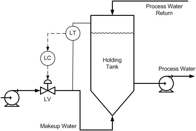
Figure 1. Process diagram with relevant instrumentation and controls (not to scale).
I asked the operators if they could put the loop in automatic control, which they did. In just a few minutes the control loop became completely unstable. We put the controller back in manual control and the level settled out. (Since tank levels are integrators, the level did not settle out at a constant value, but it settled out in a slow ramp.)
To begin my investigation / tuning, I asked the operator to make a step-decrease in the controller’s output. I was surprised by the process response. The level measurement first made a few wild swings after which the level settled out at an almost constant value (Figure 2). The long-term response of the level made sense; the initial wild swings did not. It was impossible for the tank’s level to actually change that fast – even if the control valve responded erratically. (We looked at a trend of the control valve’s position feedback signal, and it smoothly followed the controller’s output.)
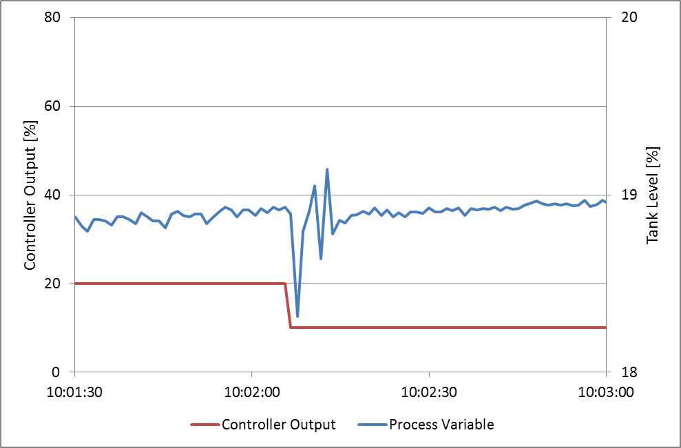
Figure 2. Erratic response from level measurement after a step change in controller output.
We walked over to the process to see if we could find the cause of the wild swings in level indication. It did not take us long to find it. The differential-pressure (DP) transmitter used for measuring the level was connected to the process in an incorrect manner. Instead of having both legs of the device connected to the holding tank, the transmitter’s bottom leg was connected to the makeup line downstream of the control valve, and about 30 feet (9 meters) upstream of the tank (as shown in Figure 1). Because of the inertia of the water in the 30 feet of pipe, a change in valve position caused a spike in pressure that directly affected the level measurement. This pressure spike likely traveled up and down the system a few times before it finally subsided, causing the successive swings in level indication.
We could not get the DP transmitter’s connection to the process corrected without a process shutdown, so we had to find a different solution. Since it was not the actual level but only the indication swinging wildly, we decided to pass the measurement signal through a first-order lag filter to smooth out any rapid changes. I used tuning software to analyze the effect of a filter on the spikes. I began by testing a filter with a 5-second time constant, but this was too short. I incrementally extended the filter’s time constant and retested, eventually ending up with a 30-second time constant.
Side note: 30 seconds is a very long time constant for a filter, and I will generally not use such long (slow) filters. But in this case it was needed, and because the level was a much slower process, the 30 seconds of additional lag went unnoticed from a performance perspective.
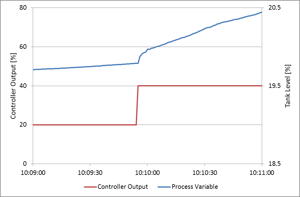
Figure 3. Step response of the holding tank level with the 30-sec signal filter in place.
Once we had the filter in place, we did a few more step tests (such as the one shown in Figure 3) and tuned the controller. We then put it in automatic control, and for the first time it controlled the level satisfactorily. The operators and process engineer were delighted.
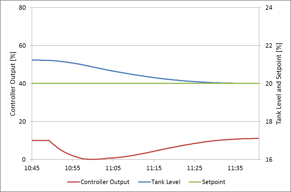
Figure 4. Control loop performing well in auto.
It is not always possible to overcome process design flaws by changing the control design, but when such a change works, it feels really good.
Stay Tuned!
Jacques Smuts
Founder and Principal Consultant of OptiControls Inc.
Author of Process Control for Practitioners
