Tank Level Tuning Complications
Level control loops are strange creatures. This strangeness can make them difficult to tune. On average, level control loops are tuned the worst of all process types. Although I have seen poorly tuned loops of all types, poorly tuned level controllers typically have tuning settings that are the furthest from optimal. Most level processes are very robust in nature, allowing them to function surprisingly well with suboptimal tuning.
But it does not have to be this way. If controller tuning is based on the dynamic response of a process, most level control loops are actually easy to tune and provide very robust control. However, as you probably know, most control loops are tuned “intuitively” using trial and error. More often than not, this approach results in poor control loop performance.
Case Study
A few weeks ago, I helped an engineer at a power plant with the tuning of a demineralized (demin) water storage tank. It was a large tank – about 40 feet (12 m) high and 20 feet (6 m) in diameter. Water was pumped from the demin water production plant into the tank, and this flow rate was manipulated with a control valve (Figure 1). Under normal operating conditions the unit consumesd demin water at an almost constant rate (most of which was discharged through the continuous boiler blowdown).
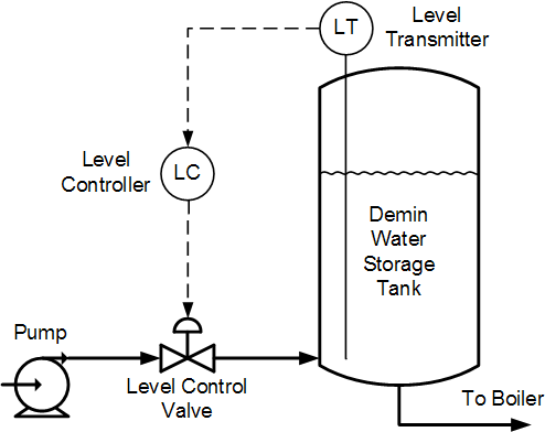
Figure 1. Demineralized water storage tank level control.
To do the tuning correctly, the engineer executed a few step tests (Figure 2) and we analyzed the data. We calculated the process integration rate (or process gain) to be 0.0045 / minute. This means if the level is at steady state and the controller output is changed manually by X percent, it will take 1/0.0045 minutes (3.7 hours) for the level to change by the same percentage. The dead time was measured to be roughly 2.5 minutes.
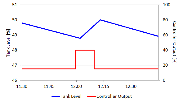
Figure 2. The two step tests used for tuning.
Once we had this information on the dynamic properties of the process, we used the modified Ziegler-Nichols tuning rules for Integrating Processes and calculated new tuning settings for this control loop. We used a “stability margin” of 2.5 and obtained the following tuning settings:
Controller Gain (Kc) = 32
Integral Time (Ti) = 20 minutes.
The high controller gain was a concern. Although the level was quite smooth during our step tests, a historical trend of level revealed some jittering was present at times. And since a 1% jitter in level would cause the controller output to “jitter” by 32% (Kc x delta PV), we decided to use a lower controller gain since tight control was not a requirement. We felt that Kc = 10 would be a good compromise between control performance and jitter tolerance.
Tuning Complications
Many level loops have small integration rates (or process gains). Integration rate (ri) is inversely proportional to the vessel’s residence time. Typically, the larger the tank, the smaller the integration rate. The process with the smallest integration rate that I personally worked with was a city water reservoir, which had a residence time of 48 hours (ri = 0.000347 / minute). For good control, a very low integration rate theoretically requires a very high controller gain, sometimes in excess of 100. Practically we cannot use controller gains of this magnitude because of the severe control action that would result from noise and setpoint changes. (Note that one can also overcome severe control action by using a noise filter and either the P&D-on-PV control algorithm or a setpoint filter).
This mandatory reduction of the controller gain brings me to the reason why most level loops have grossly suboptimal tuning settings. For integrating control loops (such as tank level), when you reduce the controller gain you have to increase the integral time, otherwise the loop can become very oscillatory.
Unenlightened tuners do not know of this requirement and end up using disproportionately short integral times on level loops, resulting in very oscillatory behavior. When they try to stabilize the loop by further reducing the controller gain, the situation deteriorates even more.
Example
For example, let’s look at how Billy, our unenlightened but fictitious tuner, might have tuned the tank level controller. Assuming he did step tests, he then used the original Ziegler-Nichols tuning rules (I did mention he is unenlightened) for calculating the controller settings. He obtained the following controller settings: Controller Gain (Kc) = 80 and Integral Time (Ti) = 8.3 minutes. He realized that the controller gain of 80 was too high, and reduced it to 10. But he left the integral time at 8.3 minutes, as calculated.
Then he tested the new tuning settings and noticed overshoot and oscillations in level. Too much gain, right? So he set the Kc value to 5 and retested the performance. The loop still oscillated with the adjusted tuning settings, but he realized that this tuning effort was taking too much of his time, so he left the tuning settings as they were and moved on to other work. Billy’s tuning results are shown in Figure 3.
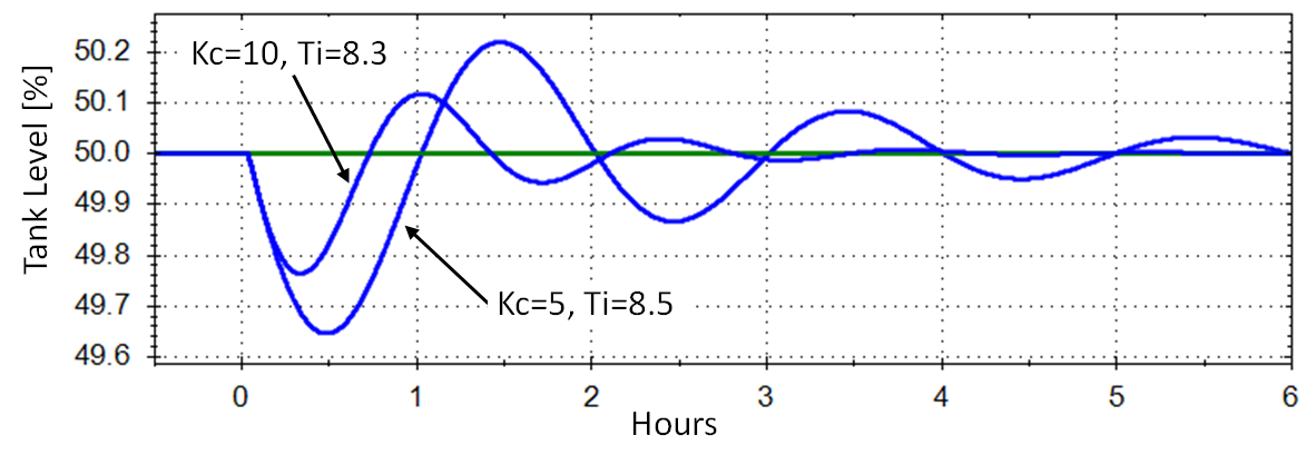
Figure 3. The result of using decreased controller gains on a level loop, while leaving the integral time at the originally calculated value.
How it’s Done
Now back to our own tuning efforts on the demin water storage tank. When the engineer and I reduced the controller gain from 32 to 10, we simultaneously increased the integral time from 20 to 64 minutes, which we calculated using the equation below.
Equation for calculating a new integral time when reducing the controller gain in a level loop:
Ti(new) = Ti(old) x Kc(old) / Kc(new)
Figure 4 compares the level loop’s response to a 5% change in outflow using the initial and refined controller settings. The control loop is significantly more stable compared to the alternatives shown in Figure 3.
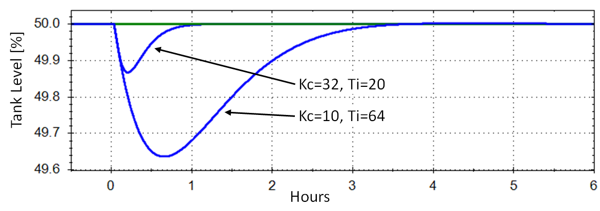
Figure 4. Stable level control loop response obtained from increasing integral time while decreasing controller gain.
As I said at the beginning, level controller tuning does not have to be difficult. Do step-tests to understand the process dynamics, use proven tuning rules to calculate controller settings, and remember to adjust the integral time inversely to any subsequent change you make in controller gain.
Stay tuned!
Jacques Smuts
Founder and Principal Consultant, OptiControls
Author of Process Control for Practitioners

Dear Jaques,
Referred to the response curve, I calculate out the ri= 0.045/min, how come to 0.0045 as said, please advise, thanks
Nhan, let’s consider the first step change, dCO = 25% in size.
Before the step has any effect, the level decreased by 1% over 32 minutes. S1 = -0.031%/min
After the step change, the level increased by 1.1% over 13 minutes. S2 = 0.085%/min
ri = (S2 – S1) / dCO = (0.085 + 0.031) / 25
= 0.0046 (which I rounded down to 0.0045 for convenience).
Hey there,
I wondered whether the control gain is equal to Kp the proportional gain of the PID controller. In some literature they emphasize that these two values are something completely different.
A response would be great.
Thanks !
Peter: Controller Gain (Kc) is not the same as Proportional Gain (Kp), because Kc is applied to P, I, and D terms, while Kp is applied only to the P term. However please refer to your controller’s documentation, because not all manufacturers follow this convention.
I think your note
“(Note that one can also overcome severe control action by using a noise filter and either the P&D-on-error control algorithm or a setpoint filter).”
is incorrect. You mean you use P&D-on-PV control algorithm or a setpoint filter to overcome the severe control action when a setpoint changes.
Thanks Tesh. I made the correction.